CAD & Tehcnical Gallery
Being an engineer by trade, a lot of my current professional 3D work has circled around CAD modeling and more precise designs. Alongside this, there are some addons and tools I've programed to make my job easier both for CAD and art work. Here, I have a few examples that highlight my experience and short explanations to go with each.
Much of my recent professional work revolves around designing utility boxes and covers that you see in sidewalks (things that say "ELECTRIC", "WATER", "STREET LIGHT", etc.). As part of this, there are several designs of covers that we needed to fit the various utility boxes and sizes required by cities and other agencies.
To meet this end, I designed a reusable template that paremetrized all the potential design aspects of these covers. Done in Autodesk Inventor, This template uses an iLogic form to show all the available options for adjusting the design. At the form's very top, the main dimensions of the cover are set. An option was available to pick a standard size to automatically assign parameters from since those were frequent. Beneath the main dimensions, a plethora of parameters were available for adjusting the markings, bolt-down slots, pick-slots, etc. There's a dedicated tab on the left for the nameplate markings since that was pretty much standard for all covers except "blank" ones. The right-side menu was dedicated to "Cavity-backed" covers, covers that were mostly hollowed out on the back side. There was a lot of experimentation in the rib-support structure that went into these covers, so a lot of the parameters available were specifically for dimensioning these ribs. The example shown is actually one of those cavity-backed designs with ribs running across the width to give the desired strength.


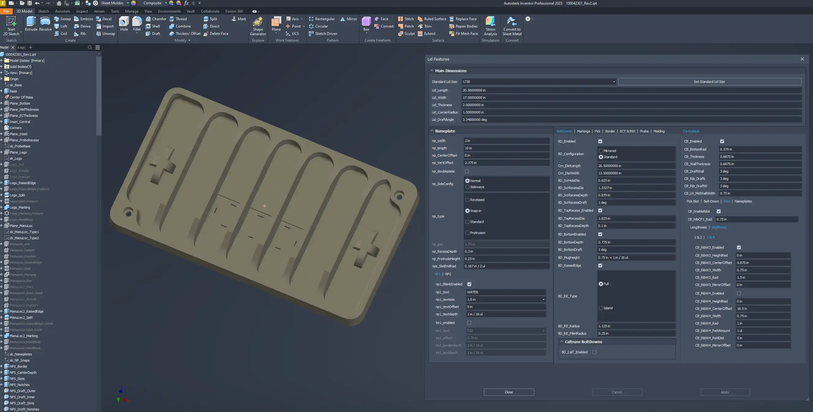
To allow all the various features and design options to coexist in the same template, significant use of iLogic was made. Anytime a radio group or checkbox parameter was utilized, there was conditional programming to go along with it. Separate iLogic rules were made for individual categories like markings, pick-slots, or cavity-backs to stay organized.
On the topic of strength, the cavity-backed designs were FEA (Finite Element Analysis) tested to determine the best geometry to use for production. Alongside this, we had to make considerations about the production process and chosen material itself since it had a huge factor on the resulting strength of the cover. In this case, simple straight ribs with large adjoining fillets worked best. The FEA simulation was done with the NASTRAN plugin for Autodesk Inventor, and the Non-Linear Static method was used. The cover was tested with it seated inside of a box as this not only mimicked the test-standard it was to undergo (ANSI SCTE 77 Section 7), but having an accurate lid-seat gave more accurate results on the bending loads experienced by the cover. The image below shows the underside of the cover with a gradient showing principal stress along with max deflection.


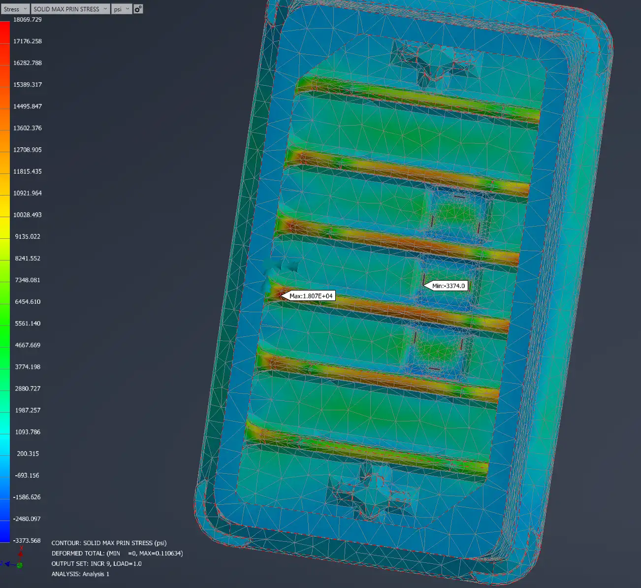
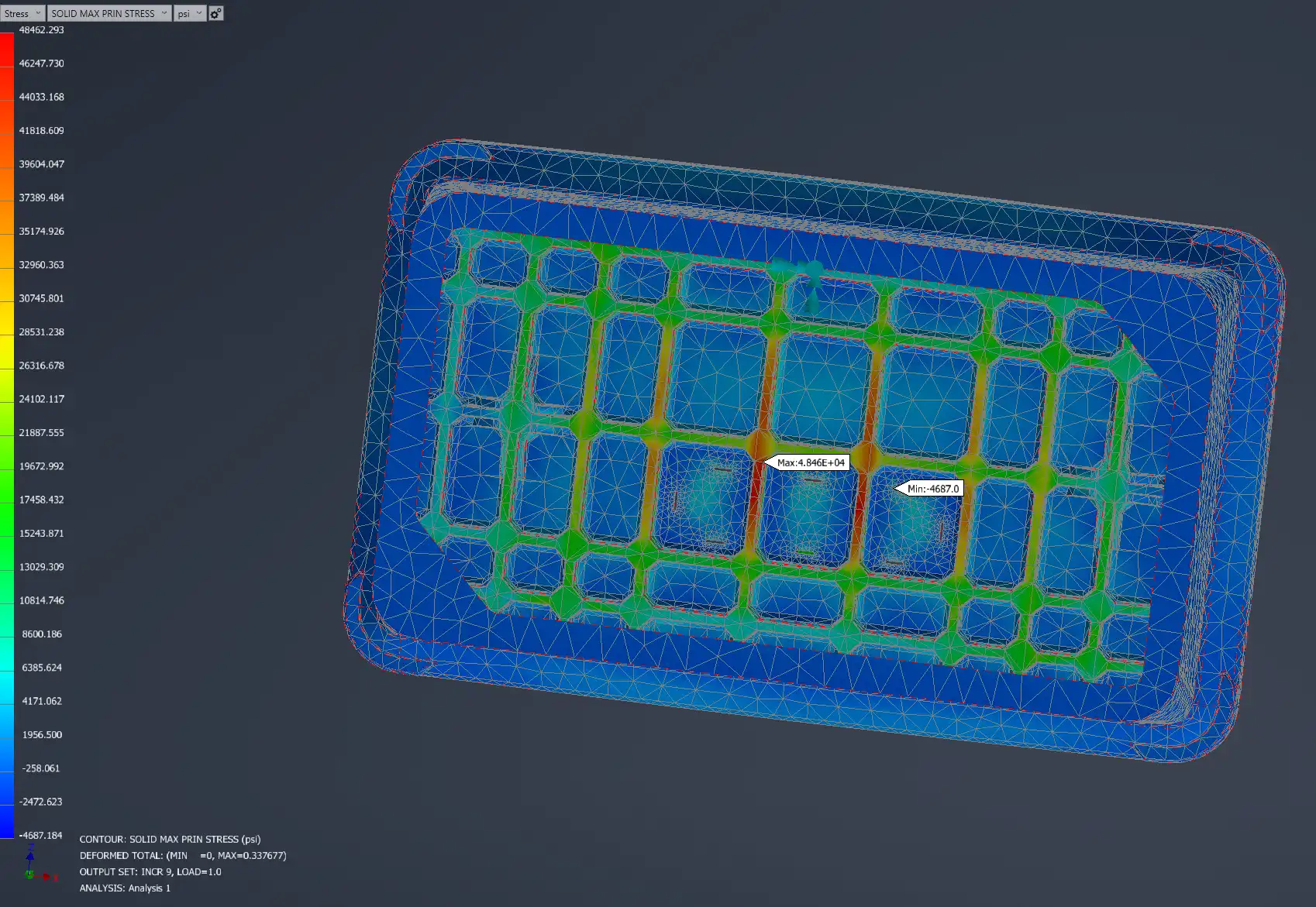
We tested other rib-designs using the same FEA setup. This next one did not test very well showing much higher stress under the same loads, but it must be reiterated that the manufacturing process for this specific material had a huge influence on final part strength. In terms of just geometry, the previous design also took advantage of taller ribs in the center of the cover while this had a constant thickness throughout the cover.


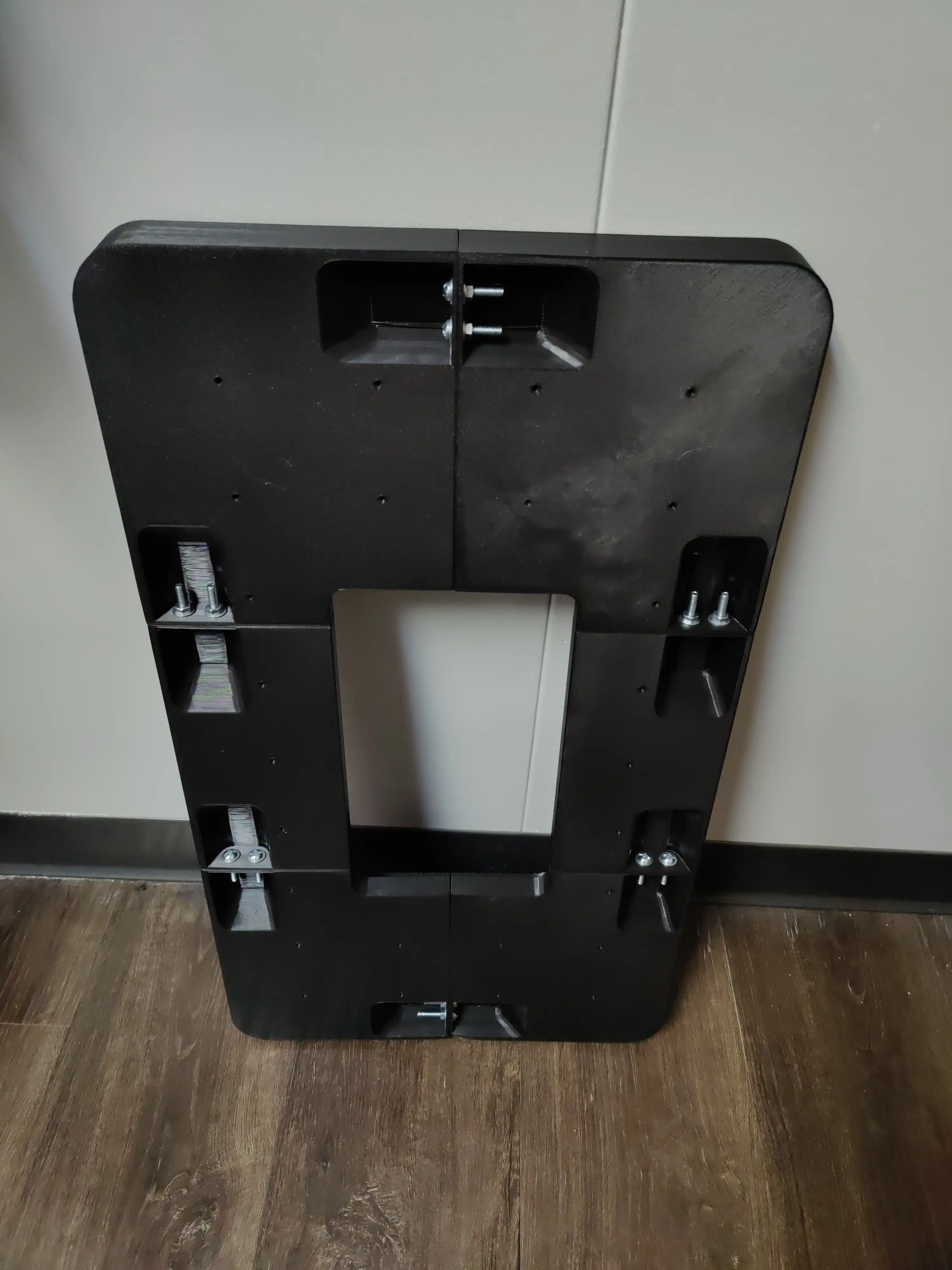
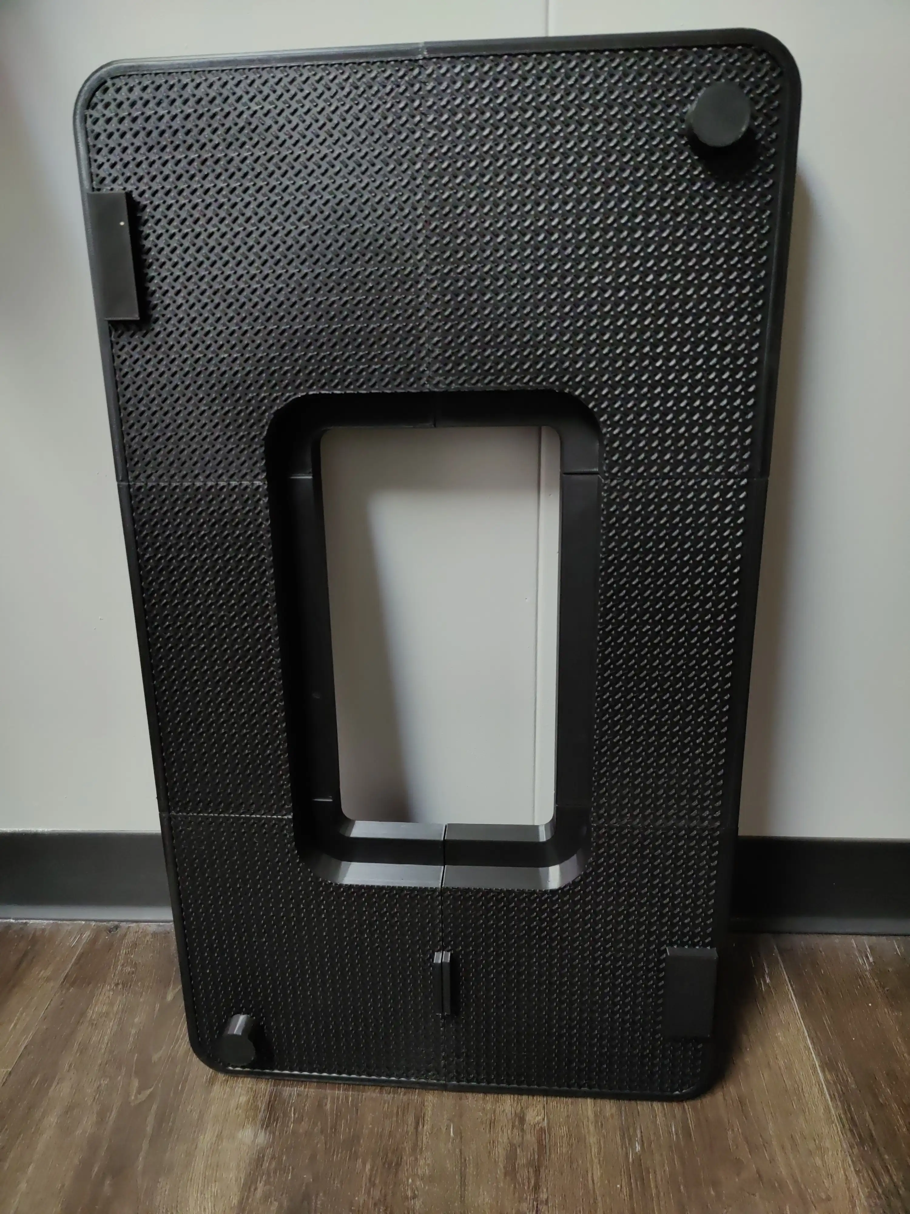
Along with FEA testing, there became a need to create molds for newer products especially these covers. Most of the molds were made from silicone poured over a master-representation part if it was not a machined specialty. Most previous master copies were outsourced for 3D printing, but this was both expensive and not very ideal for smaller one-off parts. Having experience from the hobbyist side, I set up a low-cost 3D printer with network functionality and began producing the masters and other smaller molds in-house. The only limitation with the rather-cheap printer was size: about 12" x 12" for the buildplate. I got around this by designing the larger parts with underside recesses containing holes to put bolts through. Here's one of the examples of a larger cover that was printed in six pieces and bolted-together.


Pivoting back to CAD automation, there was a previous project that involved more assembly work than part-modeling. The concept was similar in that it was also a template. However, this was an assembly of multiple pre-existing parts rather than a single part with several model features. One of the products we made known as Box-Culverts, large hollow box sections used for flood control, used a modular tooling set. Various pieces of this mold-set could be assembled to produce different sizes of product. It became apparent that having a set a plans detailing how to assemble the mold was necessary since purely leaving it to shop-crew to figure it out on their own led to many mistakes and much time wasted. Another difficulty for production was producing boxes with a skewed-face necessary for rounded sections. This became another facet of mold and design planning where we had to figure out the necessary shimming to produce a skewed face. After modeling representations of the mold-parts to scale, I made this mold-generator that would create the mold from the chosen product dimensions.


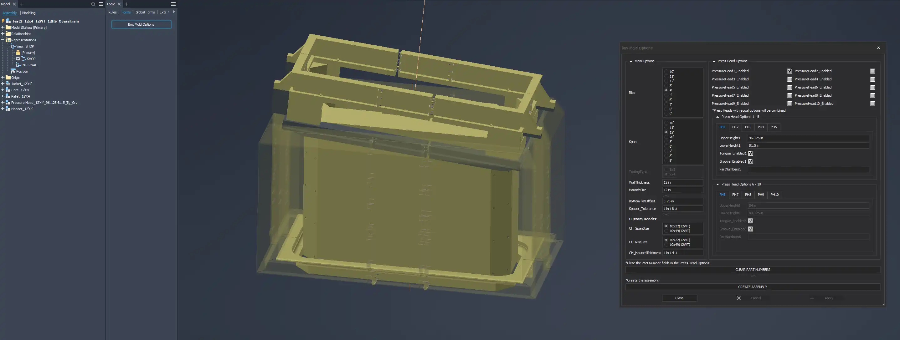
The generator would produce all the various sub-assemblies, save them out, and then bring all of them into this file. They would automatically be constrained and formed the representation of the mold assembly. Because there could be multiple sizes and skews of box-culvert for a single job, there were options to generate multiple assemblies with different shims to accomadate all configurations needed. From this, drawings could be derived detailing for production how to perform their changeovers.
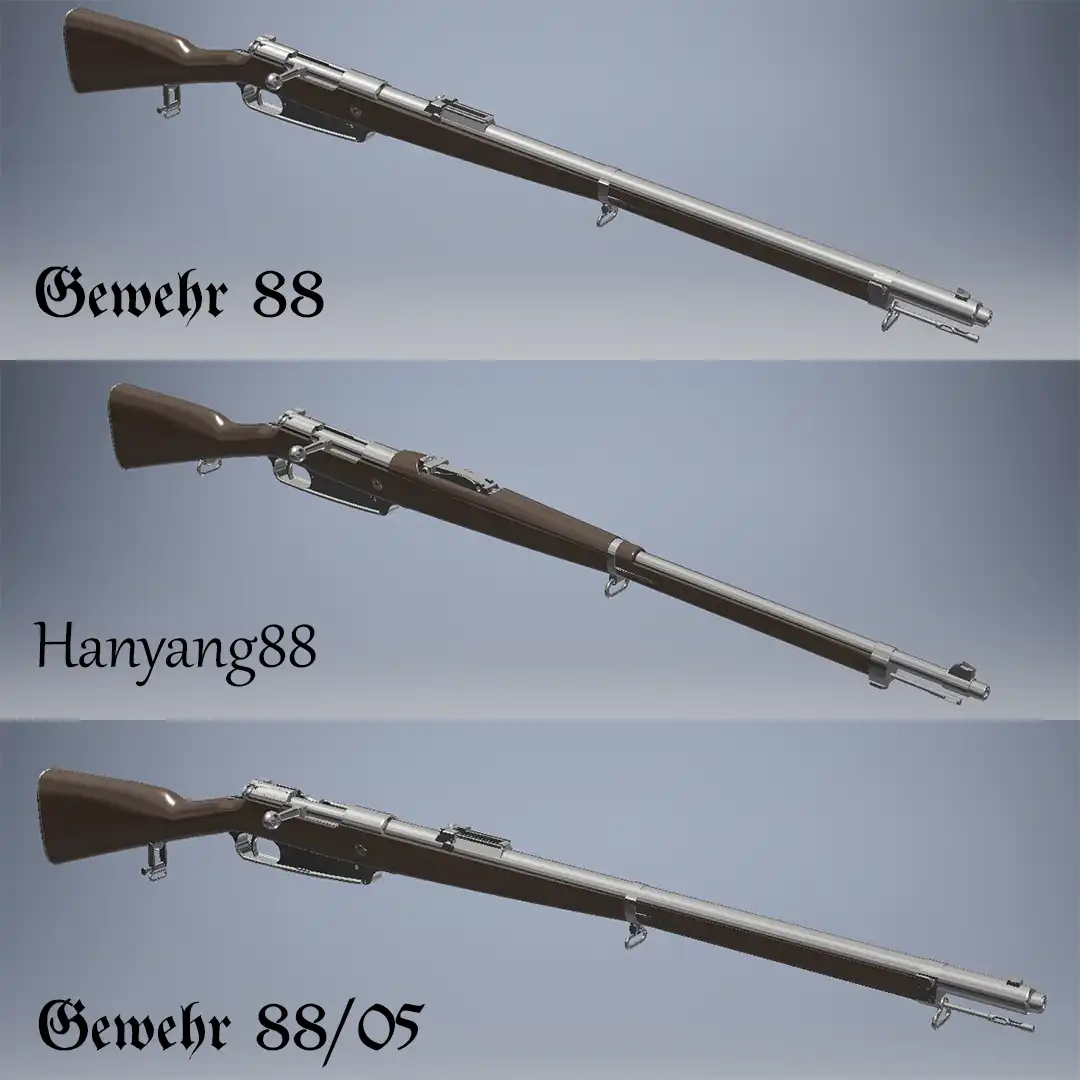
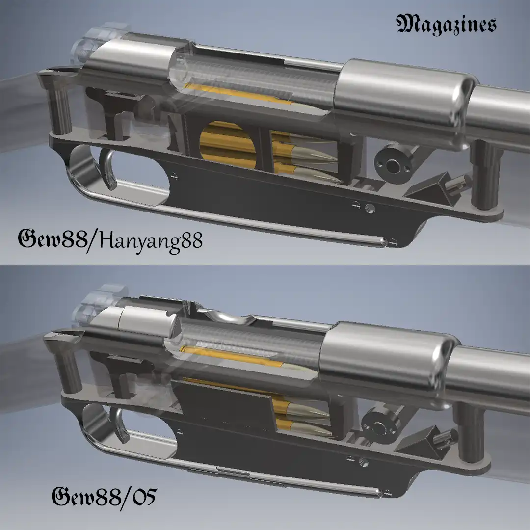
For more personal projects, there was a lot of weapons modeling done with both Autodesk Inventor and Fusion360. To get more familiar with Inventor upon first use, I took up a project recreating several variations of an older German rifle known as the Gewehr 88. This was done by taking measurements from real disassembled examples and essentially reverse-engineering it. Calipers, radius-gauges, and measuring tapes along with reference material from a collector's book were used to recreate the models as best as possible.


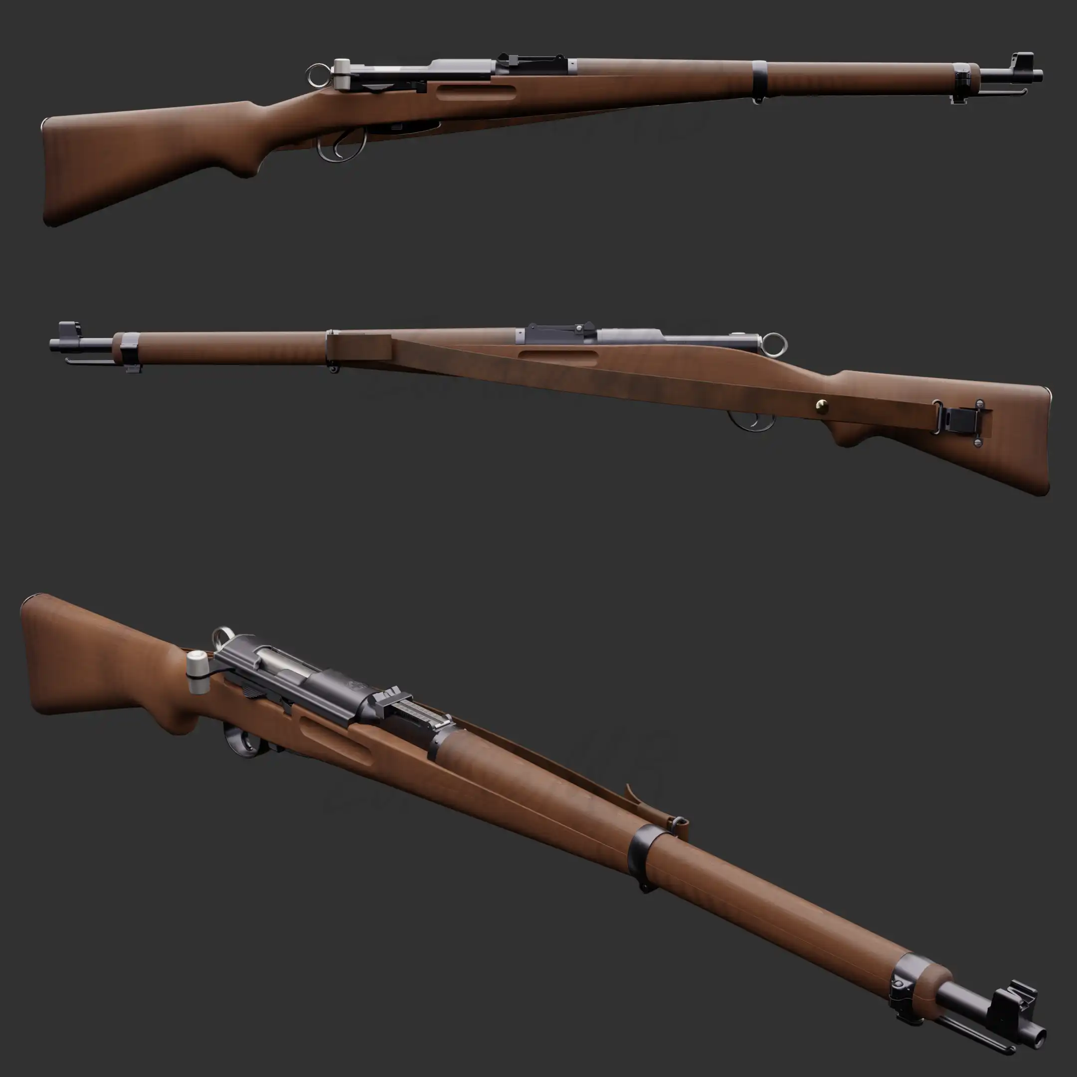
In a similar vein, another recreation project was done in Fusion360. The weapon this time was a Swiss Karabiner 31 rifle or K31. This was done not only with reference to a real example, but I had the opportunity to view original technical drawings for the weapon to make the most accurate digital recreation from. Even with the technical drawings on hand, it still proved quite challenging to fully recreate. Parts like the receiver had extremely complicated geometries like helicoidal recesses and explicit angular callouts for where screw threads were to start. The stock too was quite challenging having a lot of smooth curves defined with several cross-sections. Organic features like the stock might have otherwise been reserved for NURBs or even mesh modeling without the explicit dimensions and features being given.


This model was then exported to Blender, retopologized with clean geometry, and rendered with realistic materials. As I'm also a character artist in my free time, I've been using it quite extensively for fun and representational poses there too.


Not all my precise-design projects have stayed within explicit CAD software. Much like the exported K31 model above, a lot of my modeling work has been done with Blender, a mesh modeler used more often for artistic purposes. However, gaining an understanding of Blender's Python API has opened the door to procedural mesh generation. Nowadays, there is at least the more user-friendly geometry nodes to help with procedural generation, but the Python API still gives the most freedom with the right knowledge under the belt.
One of my best works showing this was a procedural gear generator. These scripts are able to produce accurate spur gears and bevel gears with either involute or cycloidal teeth. It will appropriately position pairing gears, generate extra gears in a train with automatically matching attributes to ensure meshing, and even create rig controls to allow for easy animation. Turning the scripts into an addon and adding an interface allows for control of almost every aspect of generation. Basic parameters like number of teeth, pressure angles, and positioning eulers are available as well as finer controls for number of points to generate (as these are mesh models rather than parametric CAD models). Something like this gear train was put together and animated in about 5 minutes with this tool.


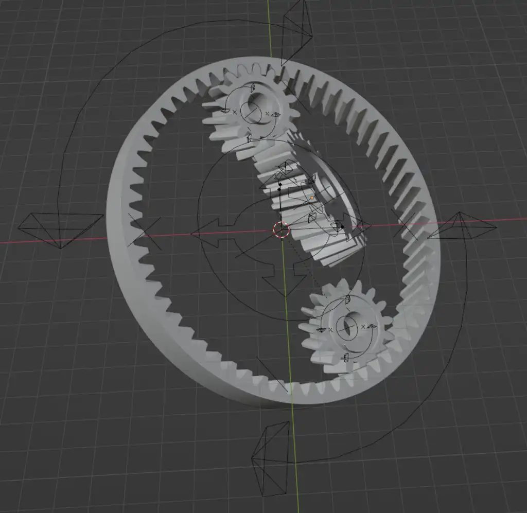


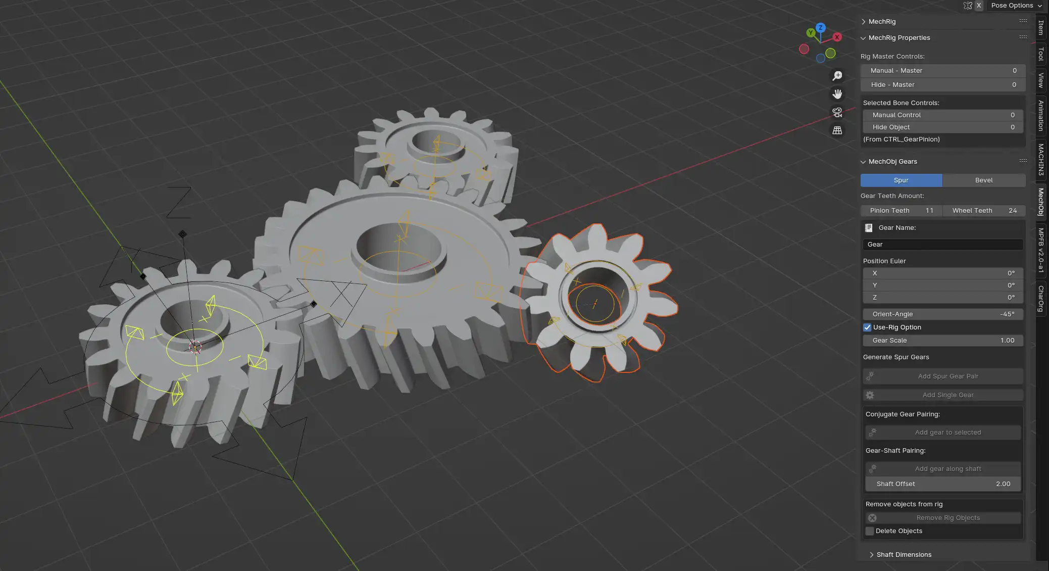
With the option of Cycloid teeth, it's possible to get gears with small numbers of teeth without the risk of undercut like with the involute profile.
There are operators in place for doing bevel gears too. This uses both spherical involute and spherical cycloid profiles for generating teeth. This is also demonstrated below with single "cross-sections" of the generated profiles to show how they get generated at a specific sphere radius.


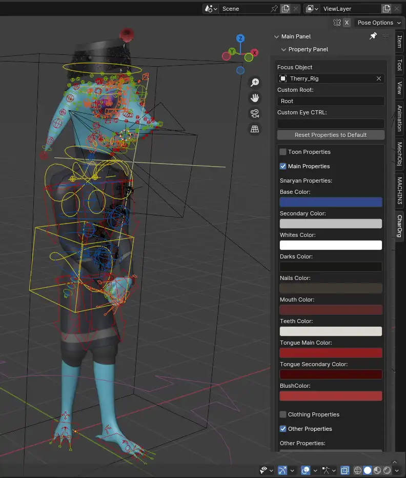
An honorable mention should be made to another add-on I've developed in Blender for character-rig management. While it is meant more for art purposes, it's another good display of tool development involving python programming and UI development. The tool is primarily meant to display custom-property controls in the side bar for easy access. Normally, these controls would only be accessable with the controller on the rig actively selected, but that can make it very inconvenient when handling other objects, editors, or rig controllers simultaneously. This puts those controls in an easy-to-read interface on the side.
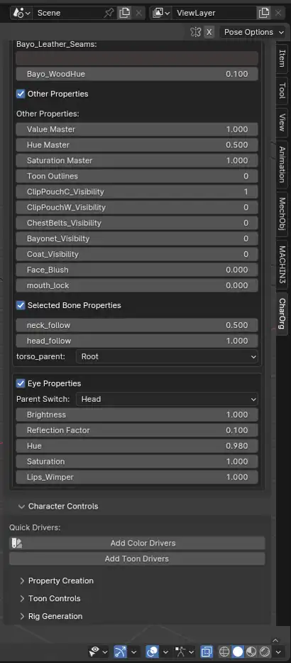
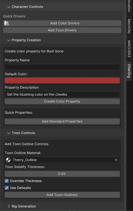
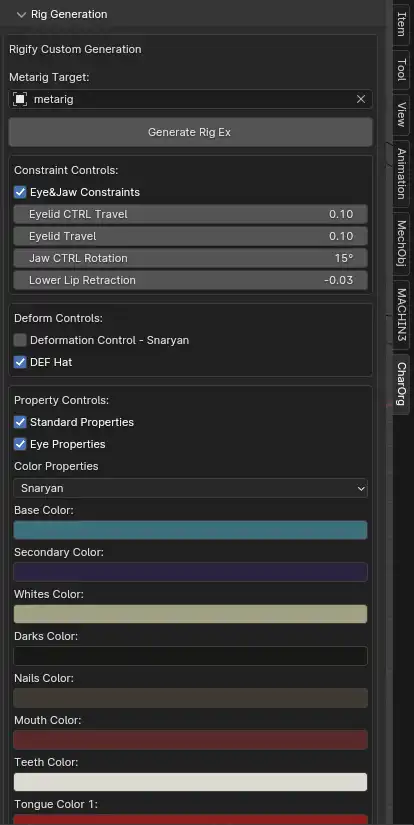
Additionally, there are operators that allow for easier creation and retention of these custom properties as the rig is created. Many of my personal rigs depend on an add-on known as Rigify that comes packaged with a base Blender installation. If I make changes or add properties to a rig that is generated with Rigify, those changes may be lost upon a regeneration of the reference metarig. Having a metarig to make easy changes to is the primary appeal of Rigify, so my add-on includes an operator that preserves these properties and custom controls with a regeneration of the Rigify rig. Along with this, there are other common custom controls that I use for my characters that I am more easily able to standardize with these custom operators. Overall, it makes the rigging process much faster, and the final rigs are much more versatile.